Electric Field on a Sphere
Development Notes:
12 - 17 - 2008
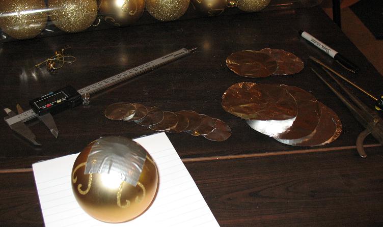
Hemisphere 1 has already been created in the last experiment.
Slide a finger along a hemisphere from center to outer ring edge and note
the sensation shifts from torsion pressure to electric feeling.
Also note there is ample energy present, without any external power, to keep this system vibrating.
If we take the point of view that the sphere represents the time domain
from inside to outside we can conceptualize how platonic vibrations operate.
Simultaneous T pulses, of equal
strength are normally at every node, and at slightly different
times at every layer, vibrating inwards and outwards.
Electric waves will travel from center of foil discs to outer ring and
reflect back inwards to form standing waves, if cut accurately.
Due to the geometry of a 1/4 wave reflection on a circular disc,
the entire disc may charge with a DC voltage much like a Joe Cell.
Sphere 1 qualities
[Last experiment]
Sphere diameter = 79.12mm
Circumference = 248.562810 mm
Resonant frequency fractal - 846 hz [as sensed using audio generator.]
We now know that to change the dominant natural vibration frequency of
the sphere we can alter its diameter, or its platonic frequency form.
To change the EM resonance we can alter the foils diameter.
Torsion moves through the mass of the ball, EM moves along the metal surfaces.
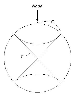
Showing propagation paths for T field vibration through the ball
(cones) and E field vibration along the surface (discs shown top and
bottom). These waves are expected to operate at 90 degrees.
This shows the connection from inflow and outflow to EM waves.
On the outer foil ring there will be maximum voltage cut on a 1/4
wavelength reflection of the E field wave found in a circle, of the
frequencies match the correct ratio the discs may charge up.
Tempic to Electric field segment length ratio
Foil hemispheres can be energized using either a balanced
segment ratio, or an unbalanced segment ratio, applied to any tempic resonant
vibration and placed at 90 degrees to energize, over a node position.
Balanced Ratio .524480 1.475378
Unbalanced Ratio .807911 1.23775977
See 925 Hz Document
Compare ratio of T rod to E and M rods as directly measured in this experiment.
Creating a motional field

Nuclear spin is reversed in Copper and Aluminum.
Thus if two of the materials come together at a torsion node they may
even produce a rotation of the E field on the sphere, that will be
reversing with
the tempic field vibration rate.
This is a side note however and not the immediate goal, as this frequency may be quite high.
Electrifying an Aluminum Hemisphere
If one measures the distance between nodes on the sphere system, and then
applies the T to EM formulas to determine the hemisphere diameter, the entire foil may become electric.
Trying first the unbalanced ratio.
T field resonant length times .807911 = Shorter electric energizing length
T field resonant length times 1.23775977 = Longer electric energizing length
With 90 and 45 degree hemisphere layering for squaring the circle and spining it at the equator.
Setting up 90 and 45 degree EM resonant foils on a sphere
Calculations:
Sphere diameter = 79.12mm
Circumference = 248.562810 mm
/8 nodes per equator = 31.070351 mm = node separation surface distance
* .807911 = 25.1020786 mm Short Diameter
* 1.23775977 = 38.457630 mm Long Diameter
Note we can double these fractals as needed to form our foil hemisphere disc to a comfortable
size and it should still vibrate up with electric feeling energy.
1x 25.102 mm 38.457630 mm
2x 50.204 mm 76.915261 mm
4x 100.408 mm 153.83 mm
Final formula:
Circumference * .4039555 = Foil Disc Diameter [unbalanced coupling]
Multilayer sphere created using above resonant sizes.
Dielectric layer also between all these layers.
Layer 1 - 6 ea 38.4mm diam 90 degree pattern
.5 mv [These are placed oppositely N S E W Top and
Bottom to set up quadrature T resonance inside the sphere]
Layer 2 - 2 ea 76.915 mm diam over 2 opposite smaller ones 1.2 mv
Layer 3 - 2 ea 76.195 mm diam over 2 opposite smaller ones
Layer 4 - 2 ea 76.195 mm diam over 2 opposite smaller ones
[At this
point we have a reinforced quadrature resonance with two sizes of discs]
Layer 5 - 2 ea 100.4 mm 45 degrees off equator
1.6 mv
[The next two layers are the 45 degree sets]
Layer 6 - 2 ea 100.4 mm 90 degrees to last layer
6 to 27 mv
Sphere feels pretty good. All foils only one layer thick Aluminum foil. Very nice vibration.
100.408 mm size feels right and
natural! As the 45 degree layers are added the sphere comes to life for
sensing. It vibrates to the touch!
Coil Trial
Wound a copper coil perpendicular to the outer hemispheres, using a
resonant length, and got a
strong high frequency radiation, hitting right top of head. I had
to destroy the coil using scissors, and get out for a bit to
discharge the energy. Somehow
the torsion field started vibrating up at extremely high levels, rather
then the energy moving into the electric field. The 90 degree, with
45 degree angles produce good torsion fields, but are not producing
currents in the wires. Down in the micro amps.
I should try one coil parallel to the hemispheres and between them.
[This needs to be followed up on after I get over the pineal shell
shock!]
I believe we may need to start moving towards tetrahedron forms at 60
degrees, to convert to electric fields. This is mainly due to an
experiment where I observed the torsion fields go quiet at 60 degree
angles. I believe the energy may be moving into the EM layers on this
form. At least I may be able to avoid the nasty loud vibration hitting the head.
See Light Technology - Locating the 60 degree angle using the Golden Rods
Mapping and Marking the Sphere for a Star Tetrahedron
As we apply the spin technology of torsion and sensing to the star tetrahedron things become very interesting.
First a little geometrical math is in order to map the positions onto the sphere.
Torsion propagation on the sphere
A vibration line or T field segment travels straight through the spheres mass to hit a node point at the surface.
We can consider the length of the line is the inverse of the frequency.
Line or rod length segment = Fractal
~300,000,000x / Line length = Frequency
These two will change together so given the ratio of the lengths we can
also find the frequency ratios using the recipricles of the lengths.
Energy couples between octaves, and energy couples between frequencies at node positions.
As you set up a prime frequency on a rod
with even nodes, both ends will spin the same direction. As you place
two prime even rods with ends together the center node will flip to
opposing spin.
Thus moving along the sphere the (inflow - outflow) will flip as we jump across segments.
The Blue lines or Star tetrahedron resonance frequency,
will jump one node and reverse spin on both ends because these are
chained, top to bottom in 3 each. Spin will be reversed. Since the Blue
lines all form squares spin will couple with aiding effects in these
loops at the highest frequency of the system. I believe this frequency
may create the highest outflow on the sphere. Resonant rods are always looped using even segments for this reason.
The Yellow lines or Tetrahedron resonance frequency, will loop as sets of 3, and all loops will set up opposition or I believe inflow on the sphere at a lower frequency.
The Diameter or prime resonance frequency
will set up the lowest frequency and set up a "like spin" on all nodes
of the sphere. Both sides will be like spin. This spin will alter
the others by unbalancing them all one direction towards outflow. If
the diameter frequency is tripled [3x] however this will reverse to
inflow only on one end. If a 3rd octave is pulsed we may see a flipping
of the system???
The three frequencies will interact to change the balance. Because
vibrations are present on spheres with foil hemispheres, using only
foils, we can support any frequency at the outer EM wave layer by
cutting accurate diameter discs and placing them on the nodes. Discs on
opposite sides of the system have reversed spin at
frequency 3. Same spin at frequency 1, and no connection at frequency 2.
The First Frequency Fractal
Sphere diameter = 79.12mm [measured with a digital caliper]
Circumference = pi times diameter = 248.562810 mm [calculated]
The Second Frequency Fractal
[Yellow lines above]
Tetrahedron side is the distance between three nodes or two segments.
Tetrahedron side = Side times square root of 2
Tetrahedron side = 45.6799 * 1.41421 = 64.60097 mm
This can be used with a compass for plotting points across the blue squares corner to corner.
The Third Frequency Fractal
[Blue Lines above]
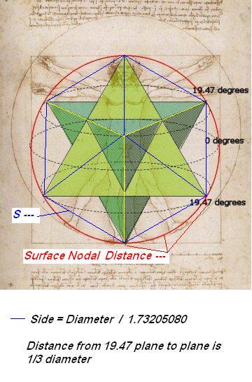
The Star Tetrahedron side length is the linear distance between node points.
Star Tetrahedron side = Diameter (79.12 mm) / Square root of 3 (1.73205080)
Star Tetrahedron side = 45.6799 mm ~ 45.68 mm
Vertical Plane Separation
This is the distance between the planes formed at 19.47 degrees top and bottom
VPS = 1/3 the diameter
Vertical Plane Separation = 26.3733 mm
If your sphere has a seam already running from top to bottom, plot the 3rd frequency distance down the seam, then the VPS.
Do this on both sides, then start laying out the rest using fractals 2 and 3.
Foil Sizes
Surface distance between nodes is the distance traveled by an EM wave between nodal points, EM is a surface effect
This is the length of the curve of the surface where the conductive foil will be setting.
If one follows the curve of the circle from equator [0 degrees] to top, [90 degrees], it will cross first
19.47 degrees at a node and then the remaining 70.53 degrees to the top node.
The ratio is 70.53 deg / 90 degrees = .7836666...
Using this ratio we can multiply by 1/4 the circumference to find our EM travel distance between nodes.
[.78366666 * (248.56281 circumference /4) = 48.96759 surface distance E field
Surface Nodal distance = 48.6976 mm
Electric Lengths
Now we apply the T to EM ratios to find possible disc diameters, because we want the E field wave standing on them.
* .807911 = 39.3433 mm Short Diameter [19.67165 mm compass setting]
* 1.23775977 = 60.2759 mm Long Diameter [30.138 mm compass setting]
1x 39.3433 60.2759
2x 78.6866 120.5518
4x 157.3732 241.1036 4x are all too large and cover over half the sphere.
The tempic field travels in straight
lines between the nodes however. So instead we just use the linear side
length to find the electric node length.
If true then the Tempic and Electric fields separate between the nodes. T follows the mass and E follows the surface. Unlike the rods the sphere splits them.
Side = 45.6799 mm
* .807911 = 36.90529 mm Short Diameter [18.45264 mm compass setting]
Side = 45.6799 mm
* 1.23775977 = 56.5407 mm Long Diameter [28.270 mm compass setting]
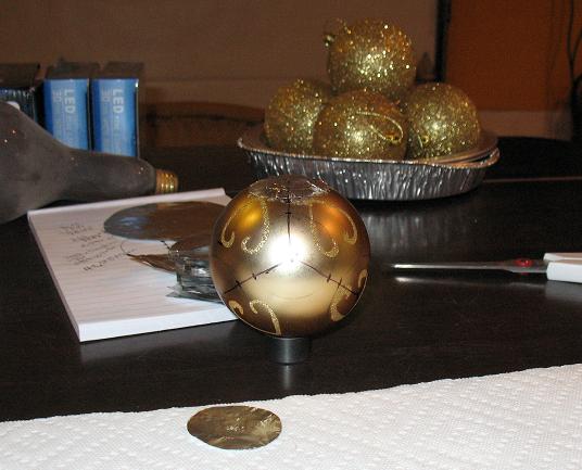
Showing sphere marked out as a star tetrahedron, with first layer disc. 39.34 mm diameter disc will fit nicely,
sized at .807911 times the nodal length. Just holding the disc on the sphere, you can feel it start to vibrate up.
To me this says that with a sphere there is natural vibrations already coherent inside it for probably all the platonic shapes.
Since all are in a harmony we will probably not get EM rotation by only emulating perfect T resonance everywhere???
We desire the nodes to move, or at least the EM nodes move.
Successive layers then may have to be somehow altered to generate say a
60 hz shift in stability. This could be done using diameter or
dielectric thickness.
Possible course:
Magnetic fields interact with the torsion fields in Bismuth at 95
degrees separation, this places the E fields at 85 degrees of
separation.
See Principle of diamagnetic fields and mind
See also Spin Coherence - Howard Johnson and coherent spin alignment
Foil sets placed at 85 degrees separation on the sphere may couple
torsion and E field, off balanced to platonic form, and do
something. Possibly a magnetic field will result, or a motional
instability, rotation, or a diamagnetic field.
See Waveforms on a sphere with a top coil
In this experiment it was shown how a scalar canceling coil at the
equator can produce an amplitude modulated pulse at much lower
frequency.
If we now instead set up a platonic resonance, can this be adapted to
produce workable low frequency EM for extraction, powered by the
spheres natural tempic field vibrations?
The scope trace reveals it may be possible if we can get the tempic
field to vibrate up strongly enough into a top coil on the nodes.
Could this be why I had a strong torsion field vibration runaway when
placing the coil on at 90 degrees to this natural angle and cutting it
to tempic field resonance vibration???
Symmetry
The electric ratio .807911 seems rather weak on a sphere with discs, compared to copper tubes in water.
Tthis is probably due to the non symmetrical ratio. The symmetrical ratio is different.
Our foils are in fact symmetrical systems around a center node.
Solving for the ratio for a standing wave in both directions producing EM from Tempic resonance.
T = 14.195 cm
E1 = 7.445 cm
E2 = 20.943 cm
Ratio for small length = 7.445 / 17.195 = .524480
Ratio for long length = 20.943 / 14.195 = 1.475378
Now using these ratios applied to our Star Tetrahedron Frequency Fractal:
Star Tetrahedron Side = 45.6799 mm 3rd frequency
Surface Nodal Distance = 48.6976 mm
Single Tetrahedron Side = 45.6799 * 1.41421 = 64.60097 mm [distance between corners - like spin] 2nd frequency
Diameter = 79.12 mm 1st frequency
We can try applying the new ratio to any or all of these and check for an electric feeling on an Aluminum disc.
Anything over 1/2 the circumference will be too large to use.
248.562810 mm / 2 = 124.281405 mm [this is our limit]
Length * .524480 * 1.475378
45.6799 mm 23.958 mm 67.395 mm
48.6976 mm 25.541 mm 71.847 mm
64.60097 mm 33.882 mm 95.311 mm
79.12 mm
41.497 mm
116.732 mm
Compass setting to create the foil discs = 1/2 diameter [radius]
Diameter Radius
23.958 mm 11.979 mm Torsion Pressure [3rd frequency fractal]
25.541 mm 12.7705 mm T
33.882 mm *** 16.941 mm Nice even nodes symmetrical [2nd frequency fractal]
41.497 mm 20.7485 mm T [1st frequency fractal is radius]
67.395 mm 33.6975 mm T
71.847 mm 35.9235 mm T
95.311 mm 47.6555 mm
116.732 mm 58.366 mm
Table must be fully explored for T to EM conversion on a sphere.
Best appears to be 33.882 mm [This is the Tetrahedron Frequency]
1/2x 16.941 mm
1x 33.882 mm
2x 67.764 mm
4x 135.528 mm [too large]
EM resonance lengths
E1
E2
Description
20.7485 mm
116.732 mm [1st frequency fractal is
radius] Top and bottom only. Diameter can have one or two segments or octaves.
33.882 mm
95.311 mm [2nd frequency
fractal] Tetrahedron 2 each Dual spin systems
23.958 mm 67.395 mm [3rd frequency fractal] Star Tetrahedron
Adding foils for the 2nd and 3rd frequencies should increase inflow and outflow field.
Now using the prime frequency to flip the system we may be able to generate EM.
If a coil is wound on the equator it may flow current during the flip, if there is a voltage reversal.
Home