An EM Sensor
[Avermenko plug]
Some good results have been had with the following tool for locating
Radiant Light Nodes in resonant light systems, as well as cold
electricity. [The AV plug]
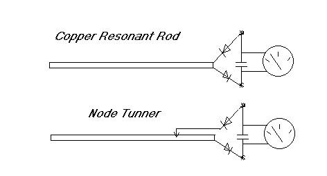
The length of the Resonant rods can be explored in the documents on the
Light Rods. Diodes can be experimented with. The meter is a volt meter
and very often can locate Torsion nodes in various feed systems, such
as Joe Cells, or density spheres. Rods were copper, but can also be
tried using aluminum and iron. Diodes are high speed units.
Feb 2008
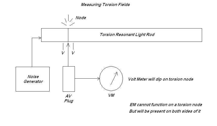
The diagram above was concieved on 8 - 24 - 8 by a Joe Cell group
working with cells in a car, when it was noiticed that the cell creates
torsion nodes on the surface of the car that can be felt anywhere on
the cars outer metal. As the AV plug shown in the upper diagram was
slid along the car it was noticed that on the nodes the meter would
allways go to zero. On both sides of the node a voltage was present.
The voltage levels were also extremely low, so it is now understood why
the noise generator is needed for torsion field detection work.
Basically the stronger the torsion field being created by a device the
quieter the EM fields become in an area. The noise floor drops out, as
the field eats it [Inflow Node].
A Torsion Sensor
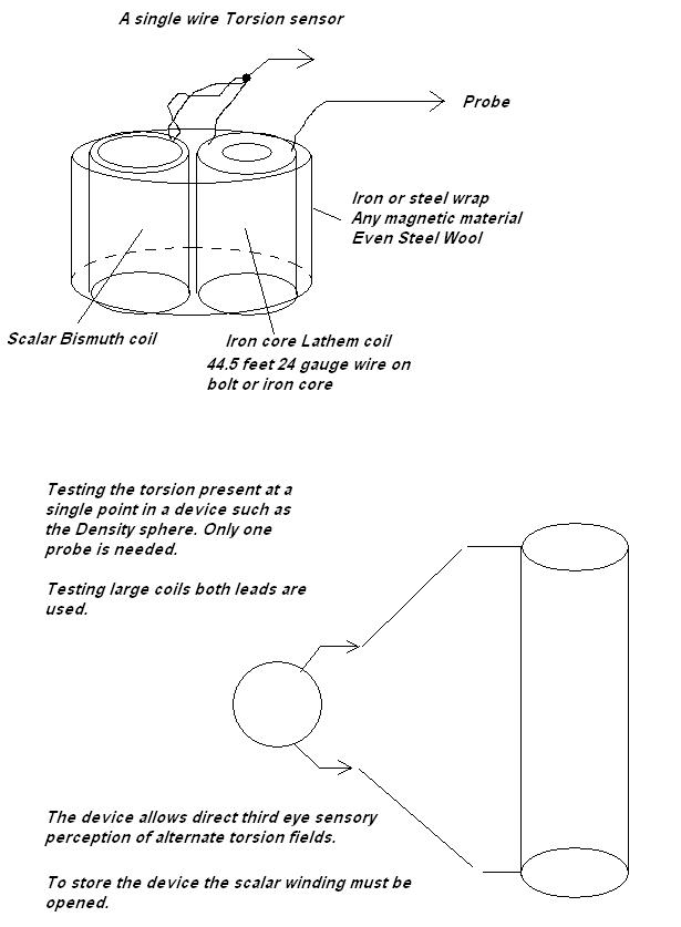
After the unit is built and the wires connected, hold the unit in one
hand and touch the Probe wire with the other hand, you will feel
the units torsion move up your hand and into the mind. This config
feels rather pleasant. The unit is self powered from the Lathem coil
and sets up a background system reference. The Torsion capture coil is
now used to draw in the testing circuits torsion state with a single
probe. The shorted scalar coil connected to one side, is setting inside
the magnetic and tempic fields and cancels the magnetic component while
it amplifies the tempic component. The unit is held in the left hand
and then the probe wire is touched to the circuit to be tested.
It was discovered that Torsion as propagates along Copper or Aluminum
is contained within the atoms themselves as an alternate "off centered"
density state of the material itself. Torsion propagates without loss
along the AG metals to near unlimited distances. To make these fields
very perceptible as they sit in coils or devices the small hand held
torsion sensor is very handy. It will take the torsion state present in
that material and turn it into a radiant field perceptible to the third
eye.
Because torsion does not follow an electric circuit, but moves along
the isotope chains of the Copper, the sensor simply uses this nuclear
flow against itself with a normal winding setting close to a scalar
winding, to imbalance it. As normal coils also contain torsion
that is not perceptible or not being cancelled, this unit can be used to find the strongest
points of torsion along a large copper coil with very large copper
mass. The tests are comparative, and sensed rather then providing meter
outputs, thus frequency does not have to be known.
Using this setup has allowed me to confirm the 44.5 foot length is a
resonant size, but also that any lengths near 11 foot also produce
stronger effects when used in scalar and normal coil series chains.
This goes a long way to explain the opened circuits often found in
devices using scalar coils, as the energy will actually flow along a
single wire to fill any mass of AG metals it touches. This also makes
switching of torsion circuits a difficult task as physical touch is all
that is needed to switch torsion through, and it often will move right
through the insulators in switches, as it propagates along the nucleus
of the isotope chains.
If used for both torsion and electric tests, both leads on the normal
coil are used as probes, and connecting them to a large coil will
greatly increase the output of this unit. This also shows that copper
mass is an important element in scalar coil designs.
As scalar coils interact with normal coils more strongly at close
proximidity, using this unit to measure torsion points close
proximidity to the coil being tested is now not necessary because the
unit offers the field interaction. Long clip leads can be used between the coils and the test unit.
David Lowrance
March 4 2007
Measuring Time Shift Effects
While measuring time shift effects
may seem simple if one is thinking only about time flow rate, we must
also consider the effects of the device on all the density parameters, or individual field forces.
That is, as the background spin field is altered in an area, other
effects will be observed that may make such devices not function as
expected.
As the background tempic spin is altered over an area from a central
point, a spin effect is generated that will spread out dropping off as
a function of inverse linear distance. This time skew will also effect
any voltages passing through it and as well any magnetic fields. A
device must be designed to account for these effects also. If it is
desired to compare, we need to locate one sensor outside the altered
tempic field for a reference and one sensor inside the area near its
center.
We can expect a time effect to be very small from a 1G to a 0G gravity
as the GPS satellite system shows us only a few cycles per second at a
Gigahertz frequency. However a voltage moving across such a field would
experience a tempic squared effect and a magnetic field a tempic cubed
effect for field intensity.
1 - If we are inside a higher time flow rate area with a meter reading
a voltage provided from a voltage regulator located outside the area,
we should see an effect representing the square of the change in the
tempic field.
2 - If we are able to make a magnetic field somehow stretch from
outside the area to inside the area, using copper clad iron wire, and
able to measure the magnetic field strength inside the area we should
see it effected by a cubed factor compared to the tempic field
gradient change.
3 - If we locate crystal oscillators in both areas and provide them
both with internal voltage regulation at the oscillators, we should see
a frequency shift between them representing the time shift directly.
These would have to be extremely high in frequency and in stability.
They can be monitored by pulse counters and run for a long time to see
how far apart they have wondered. It is also unknown if a voltage
regulator itself would not be effected and actually produce a different
voltage because of a tempic effect.
The most practical method for experiements, in a local area
where magnetic spin altering devices are being tested would be a
voltage regulator system with a super accurate digital meter panel
display. Since a frequency shift of 1 cycle in 1,000,000,000 Hz [Ghz]
would represent a very large alteration to gravity, we would need the
[square root] of this ability on a voltage reading meter. Resolution
to 5 places or more. The higher the voltage the better, as it
will be seen as a percentage of the overal voltage changing. The time
base crystal in the device will experience a linear tempic effect but
the voltage a tempic squared effect.
There is one other device that may prove usefull. The time domain
reflectometer. This is a radar that measures the length of a pair of
wires that are twisted together as telephone cable or even Cat 5
computer wire. The TDR can be located outside the area so its time base
crystal is not effected. Then a very long coil of wire placed near the
device. As the TDR measures the time it takes for a pulse to propagate
to the end of the wire and then to reflect back to it, this will
measure a change in the lightspeed propagation through the wire in the
effected area. The longer the coil the more accurate the measurment
will become. This would apear to be the most trustworthy effect as only
the wire is placed in the alternate tempic field.
All these methods require a connection to the local earth background spin field as a comparative indication.
Measuring the background Aether spin, Density factor
It would be nice to be able to take a device on a ship that may sit
within the altered tempic field which can be calibrated to reflect
Desnsity and time flow rate directly without external reference. This
would have to compare the interaction between the tempic, voltage, and
magnetic field directly then monitor the changing ratios of energy
moving between them as the tempic field is altered. Until which time we
can monitor the above type devices for a reference, few reasonable
devices are suggested. The H coil is one idea that may show some
promise. There is a strong possibility
that as we move through density these ratios simply do not change and
the only real way to tell will be with a dual spring scale sitting
under our chair that simply monitors our change of weight.
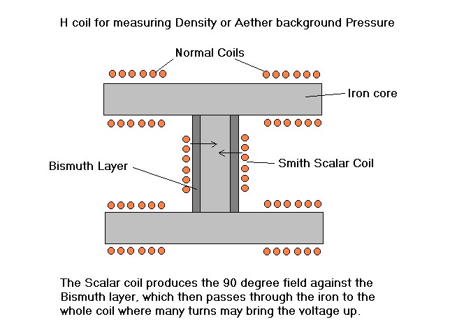
The H coil
The H coil would have a center piece consisting of a small iron pipe
coated
with a bismuth layer. This is wrapped with a Smith coil, The
outer
H structure is iron, wrapped all the way around with a normal coil
winding, or four pickup coils in aiding wrap on each H leg. The two
coils set at 90 degrees to one another. The 90 degree flux will travel
easily through the iron inside the scalar coil and appear in the H
structure iron core with poles to each end. As AC energy is placed
across
the Smith coil at the center an output is seen on the normal wound iron
coil indicating the Proton to Electron 90 degree field moving
perpendicular to it through the whole structure. As density is altered
the magnetic coupling between the coils is increased and the output
voltage is seen to rise above the normal voltage ratio moving through the coil before. We are measuring the loss of energy in the transformer.
This coil structure would also be seen to harness the 90 degree flux
for amplification and clear analysis. It's input to output
ratio will be a tempic squared function [voltage] and may indicate the inverse of "gravity" directly.
The square root will indicate tempic flow, and this number cubed will
represent the magnetic field strength as well as the overall 3
dimensional time flow rate experienced within that magnetic field. As it is really unknown how a voltmeter will be effected by a tempic change this is totally theory at this point.
Home