Developing Over Unity Power Systems
This article superceeded with a more recent study found here:
[Theoretical discussion for Over Unity systems and project goals]
The basic goal of this project is to light a bulb to full brilliance
without drawing any power from the mains.
The unequal compression of magnetic poles, where one pole of the
magnetic field is skewed into a smaller area of space then the opposite
pole. It is theorized that in this arrangement the c velocity constant
is altered towards the compressed magnetic pole, and the tempic field
forms a gradient between the unbalanced poles. - Scalar coils stop currents and pass
alternate tempic field stress. In this state negative resistance is experienced.
Wilbert Smiths device showed us - spinning
a magnetic field [spinning magnets] creates gravity - he got a
1% gain
Otis Carrs device showed us - spinning
a diamagnetic field [spinning copper cones] creates anti gravity
In the second system we see magnets pulsing spinning copper cones - the
diamagnetic field wins - it expands to a stronger state then the
magnets hitting it.
It is not so much the fields then the materials involved. The Copper is
only diamagnetic when a magnetic field is present for it to interact
with. The motion expands the diamagnetic field in the copper. The fast
pulses avoid the recoil of the slower opposing field. These copper systems exhibit Over Unity
properties.
Understanding the Conical Coil and Pancake Coil
The Magnetic field around a wire
If you take a single copper wire that is straight, flow current through
it one direction, you will get a spiraling magnetic field. The field
interacts with the outside world but also it interact with its own
nuclear magnetic fields coupled into the mass of the copper. There will
also be a shift of the nuclear mass spin angle as the current is
applied and removed. The current and magnetic field will follow the
voltage of the wave by roughly 90 degrees. As the current passes the
zero point the voltage will be maximum for AC waves and setting on the
electron shell.
At any one point the magnetic curve around the wire, almost 90 degrees
but skewed slightly,
has a north pole leading and a south pole lagging the direction of
current flow. The magnetic field forms a loop around the wire with
poles buried in these loops. When winding coils, to get a magnetic
field to become coherent and pop out as one large field,
this happens along the sides of the wire where the fields aid
between turns and not where the fields oppose. Aiding fields become
coherent forming one larger field with only two poles and one blotch
wall. Opposing fields break down and maintain their own poles separated
from one another and pushing against each others fields. Thus magnetic fields grow out of the coils
along the aiding alignments of the curved magnetic fields wrapping each
wire. They form between the electron
shells of the copper atoms that are in close enough alignment to
become coherent fields.
They then disconnect the sections of wire that oppose where smaller non
coherent opposing fields start to push flux lines apart. It is the
opposing fields that expand the envelope of magnetic flux.
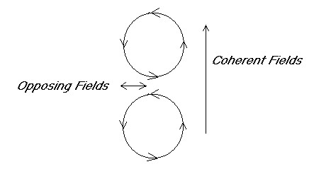
In this diagram we see the magnetic field spiraling around two wires
that would be moving into the page. The arrow tip is the North pole and
looking into the tail is the South pole. Current is flowing the same
direction in both wires, and we see a coherent magnetic field growing
along two sides of the wire loops. Between them an opposing field
expanding away as it meets opposition. Magnetic poles form at top and
bottom with blotch wall at the center, and side to side becomes neutral
with many N S reversals and many separate poles with separate blotch
walls.
If we wrapped a spiral coil of iron wire around a copper wire we could
expect to capture the maximum magnetic field from the current flowing
inside the wire.
On the ends we could rout the magnetic field with the iron wire and the
electric field with the copper wire. The iron wire should achieve field
coherence very quickly end to end having only two poles and one blotch
wall.
Normal coils [sinoid coils]
With a normal coil these magnetic fields aid one another inside and
outside but in the gaps between the wires they oppose one another. This
creates a balloon effect and pushes the field larger outwards between
the coils wires. Magnetic poles form at top and bottom of the coil and
are the same size on each end, little tempic unbalance is present.
Along the sides of the coil we see a tempic component near the "blotch
wall" sides of the coil where opposing fields push the field outwards
and widen the donut form. The
magnetic field is denser on the inside of
the curve of the wire then on the outside and this is why one
pole
dominates in a normal coil and sets up a coherent field encompassing
the entire coil vertically. The inner pole direction has a higher flux
density then outside the coil.
Pancake coils

In the pancake coil the fields above and below aid moving sideways,
moving the magnetic field outwards, but up and down they oppose. The
coils poles run around the wire and no one pole pops out to dominate
top and bottom or side to side. Canceling fields run up and down and
aiding fields run
side to side. The side to side fields grow to a coherent
state.This sets up a Rainmaker type field with one pole
compressed inwards and one pole outwards both top and bottom! This is
the reason a tempic
field is formed using pancake coils. As the magnetic fields become
coherent jumping from large loops to smaller loops the poles are turned
inwards and compressed.
With a compass you can see a sharp flip of the magnetic field at the
coils outer edge where a very strong N flips to a strong S. There is no
real
blotch wall area of any length. On the top and bottom there is a side
to side field smaller on the inside radius. On top if a South pole is
turned outwards then on the bottom a North pole is turned outwards.
In the conical or funnel coils the bottom is compressed inwards again
and one pole becomes dominant overall. The compressed pole become the
dominant one.
Stacking pancakes
Growing fields in pancakes.

To bolster the magnetic field produced, we could place iron washers
between opposing pancake
winds and develop stronger distortions of the circular
coherent magnetic fields. The diagram above illustrates a reversed
current in the center coil, or a reversed wind direction. On each layer
a different pole would dominate
moving outwards. If we place the iron on every second layer it would
increase only one pole outwards.
In the diagram below each coil is the same wind, we end up with a normal coil and a maximum
cancellation of the fields possible inside,
canceling on all sides of each wire. This design would offer the
maximum scalar canceling effects possible
for the geometry of wire. [Aiding fields increase the density, and
opposing fields lower the density.] However now we see long poles
forming on the outsides
of this coil. If iron was introduced so that none of it appeared in the
aiding places, only inside the coil between the turns, avoiding the
outside, then no coherent fields would form. A coil thus wrapped
normally would become a scalar canceling coil. A coil wrapped with
iron wire inside and no iron outside the turns would become overall
magnetically scalar canceling.
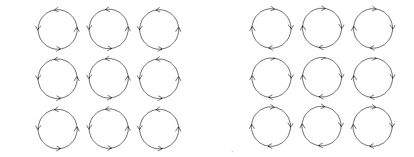
You can see there are two ways to stack pancake coils and each offers a
different result but both will have density
lowering effects.
A density lowering effect should increase the velocity of light speed.
[One of these configurations may be similar to what the cells
Stubblefield was building do with both iron and copper wire very
carefully wound.]
You can also now see that to create the strongest possible vertical
magnetic coil is not as simple as just wrapping the wire around a nail.
Since you can never eliminate all the opposing interactions you can
even used reversed currents and only add iron where you want field
coherence increased. In scalar coils you add the iron where no
coherence can possibly form, thus any coil wind can be altered to run
into the scalar canceling mode.
Scalar coils
In the scalar coils we are removing all the
vertical opposing magnetic fields by running reversed wires between all
wires on the tubular coil stack. It
is the opposing fields that cause the magnetic fields to grow larger
and extend outwards in a magnet. We
think of scalar coils as canceling the magnetic fields, however if you
look closely at the vectors between the wires you will discover
sideways
gaps aiding, and vertical ones are opposing. The field collapses
downwards disappearing but emerges outwards around the sides with one pole out and one pole in. This
rotates the magnetic field 90 degrees and compresses one pole inwards.
The "one pole out and one pole inwards"
is the reoccurring factor in all these tempic field coils and relates
only to wire geometry and direction of electric current.
Pattern noted
You can see that all coils have both aiding and opposing fields due to
wire geometry. They vary in where coherent aiding fields form between
the opposing ones.
The basic pattern we see everywhere in all these scalar devices is the
compression of one side of the magnetic field inwards. Now moving
energy through this field seems to alter c velocity, and maybe we could
pin this down better as we have a feel for what is truly happening.
In the RainMaker base the hottest torsion field is on the inside
between the bismuth coil and the iron outer shell, just poke a finger
inside and this will become obvious as the sensation is one of almost
burning energy. This is inside the single compressed magnetic pole
turned inwards.
The unequal compression of magnetic poles - would seem to be the
obvious key to producing tempic field effects, as well as the
natural link to operate between tempic fields and EM fields.
Conical coils

The conical coils produce a larger
magnetic field under the cone then over it,
this is the same pattern, pushing one pole of the coils into a smaller
space and getting a tempic field component to emerge. In these cases
people are still puzzling over just what this accomplishes, but OU
effects
are seen in these setups according to many of the experimenters.
Opposing field vectors are replaced by T for tempic or density lowering
areas. The T fields are meeting with a skewed angle in the conical coil.
The conical coils give us an interface where EM is stronger along the
opened end and nearly absent on the tips where tempic field is slowing
c.
Wilbert Smiths tempic field model fits this perfectly, and now we can
understand the conical coils.
Narrow tip is the tempic field end -
Wide opening is the magnetic or EM
side -
The conical coil, as an electric coil, is a conversion coil compressing
one end of the magnetic field. The magnetic field is a function of
current in the wire or the presence of a magnet. The tempic end will
couple to the crystals or scalar coils. The magnetic side will pick up
EM like crazy and should couple to EM or sinoid coils.
A natural progression would be sine coils - conical coils wide end -
conical coils narrow end - scalar coils. Energy should be able to flow
directly through this system either direction from tempic to EM sides.
The above observations lead one to consider a Tempic to EM converter
using six conical coils with tips inwards [cube] to a 44.5 foot hi
energy tempic ZPE scalar coil set or a density sphere center. Outside
the wide ends we experiment with EM sine coils at different angles
looking for DC and even possibly using high frequency diodes in the Mhz
frequency ranges. This setup may begin to produce useful currents in
some configuration. All six EM coils would be in series like in the
Searl IGV.
If one works up a crystal that resonates at 1 to 2 Mhz for the scalar
coil core at the center, we may see a resonance as well increasing the
output to very high levels of EM. Magnets can be used for tunning the
copper in the system to match the crystal frequency if necessary.
Interfacing both tempic [ZPE coils] and electric fields into the
conical coil shows that approx 2/3 distance down from the tip a tempic
or torsion node will form where the two fields cross in some kind of
resonance. In a free standing conical coil the torsion node can be felt
using a finger tip. Start at the tip feeling the high torsion end
first, then compare it to the opened end. Next now slide the finger
along the sides to locate the torsion nodes.
Incorporating geometry
Transition of icosahedron as coils inwards to a point form with 12
points, [the vector equilibrium form] may produce a natural conversion
system.
ZPE coils in the center could be scalar 32 foot or 44 foot earth grid
resonant. Either a system of many scalar wound coils in the platonic
form, or density sphere with crystal center, or simply many pancake
coils converging in a small space around a center point.
At the 12 points of the vector equilibrium, the conical coils move
outwards to form the icosahedron with 12 flat surface ends. Thus the
natural transition between the point forms and the surface forms to
transform the energy from tempic compression to EM expansion. The
system would have a tempic field gradient inwards, and a single
magnetic field pole stuffed into it from all 12 directions if
current
is passed through the conical coils. Once EM is started to flow in the
12 conical coils it may become self sustaining from the tempic gradient
alone as DC or possibly as a resonant pulsed DC of some form.
Before the EM field is set up in the conical coils the wire would be
aligning all the nuclear fields 90 degrees to where it is needed to
turn inwards, so to lesson the energy needed to start the process,
copper lengths can be run inwards along the coils as radials. The
proper nuclear mass should tend to reduce the tilt energy required.
Now any energy moving from inside to outside the device would
experience a c velocity increase. The conical coils tips would be
connected together to form one feed wire, and the outsides would form
the other wire, for the primary
of the tempic amplifier system.
This section represents the tornado where only a little feedback is
necessary to sustain the flow.
Secondary sine coils outside
the system would tap each current loop and these are wired all in
series. Electronic regulation could then be inserted to regulate or
govern the load by sending the proper feedback to the primary side of
the conversion system.
A simpler system could be set up as a cylinder device with conical
coils around a single scalar tempic coil system. The coil is used as
the center and the tips of the cones all move into the pancake wound
coils. Pancake coils could be placed at any angle along the conical
coils to increase the tempic gradient towards the center. these coils
are operating at 90 degrees to one another. Density is higher inside
the system where c velocity drops in space. Coils will operate in
either tempic mode [no electric flow], or electric mode where currents
are used to steer the magnetic fields to turn them inwards, or release
them back to a sideways alignment or rest state.
Basics
It is important to understand the difference between coil types as
Copper wire is a multifunction material. Copper is magnetic at the
nucleus but not at the electron shell unless electric current flows.
Copper becomes diamagnetic in a motional magnetic field. Copper becomes
tempic in a fully canceled magnetic system.
In a tempic or ZPE coil, the
magnetic field of the nucleus of the copper sets up an isotope line
where nuclear magnetic fields align with the length of the wires or the
longest geometric dimension of the coppers mass. This is also the rest
state of non energized electric coils. Wires are now formed into
special geometries to effect the tempic fields operating between wires
and in special wire lengths.This can produce a very strong tempic field
gradient in non energized coils. Conical coils have a tempic gradient
as do density sphere scalar coils, mobius coils, bifillar coils, and
the weave coil.
In electric coils the
magnetic
field is set into motion and turns from its rest state, altered by a
field that is emitted from the electron shell of the copper atoms as
electric current flows. With AC the field rotates, with DC the field
turns 90 degrees and remains fairly stationary but still has a
precessional motion around the angle of tilt. With DC pulses we can
have a 90 degree turn, or this can also flip over depending on
frequency, mass, and dimensions of the copper mass. The electric field
can turn much faster then the nuclear magnetic field which is coupled
to the mass of the copper atoms. Electric coils generate a back EM
pulse with reversed electric polarity due to the lag of the nuclear
field.
Stopping the destructive costly currents
In a powering system, it is
the
current that generates the magnetic field, but it is also the current
that generates the "heat" in the copper wires. If we take power from
the mains, [AC wall outlet] and run it directly into a scalar
canceling bifillar coil, as the two opposing magnetic fields rise they
meet opposition and stop flowing after a short pulse time for the
magnetic field to rise enough to meet perfect opposition. In this state
we have the power pushing against itself and this sets up a stress in
the tempic field.
Now as the voltage builds up in the coil it meets a perfect magnetic
blockage from the opposing direction. The
current in the coil stops flowing
but the voltage stress continues to be present across the coils two
windings. This stress moves into the copper atoms as tempic field, and
if using a copper tube core it
travels down the copper tube as pure tempic field. The energy is
present in the copper tube but no EM sensing equipment can register it.
This kind of energy flows down copper wire just as easily as electric
currents, actually easier because there is no heat generated in the wires
and there is only one wire necessary to carry the alternate tempic
field with respect to the background tempic field that is everywhere
around us. The one wire carries both sides of the stress with the EM
canceled.
To extract this energy we can wrap two coils, set them at 90 degrees to
one another around the tube, wire them in series and out pops the EM as
a sine wave.
Angular alignment of the two coils is necessary to form a sine wave. If
the one parallel to the tube is resonant at the tempic frequency and
the one at 90 degrees is resonant at the EM frequency we should get the
maximum power out possible and little will be lost in the copper. If
the coils are also 7-T to 11-E wavelengths both will resonate both
waves in series.
Maintaining the power factor is a practice already in use by power
companies, telephone companies, and antenna systems. In transmission lines it is good to
have a balanced X(C) and X(L). Capacitive
reactance and inductive
reactance balance at resonance
and the energy shoots much higher with less losses.
The problem to OU systems is that as the current flows we get resistance.
If the resistance is from electrons jumping atoms, then we start to pay
for the losses in heat and money as the power meter starts to spin
faster. The tempic field from a power meter spinning is what we desire
to avoid in OU work
It is proposed that if we use EM energy coming out of the Scalar coil
input system it be kept in resonance. If possible the load will run off
the negative resistance side of the waves and shunt any positive
resistance around it back into the capacitive side of the circuit.
Negative resistance
The notion of negative resistance
has been well spelled out in previous works of others. It is my
suggestion that we need to identify where this happens in copper
systems so we can begin to use it.
Formerly it has been noted that there are two methods of creating a
negative resistance:
1 - Capacitance
2 - Square waves
In the second case it is only the leading
edge of the square wave or the trailing
drop that carries this element of the energy.
With capacitors it is their ability to deliver instant voltages with
almost no internal resistance to slow the propagation of the energy
wave. This is Tom Beardens model. The E vector potential moves into
the copper wire faster then the electrons can flow into it. While a
coil collapsing delivers a slow building voltage and current moves in
the wires as it discharges its energy, the capacitor can deliver the E
vector first at c velocity down the wires before the current flows.
When you look at the copper interactions, what we see is that it is the
pulse into the atoms, before the current starts to flow, that exhibits
this negative resistance.
Once current begins to flow then the negative resistance gain is
outweighed by the positive resistance, and the circuit moves into the
heat loss mode and starts to destroy the source of the energy, then the
money starts to flow towards the power company.
What has not been related as of yet is how to use this energy in
copper such that we power something without drawing current.
Extremely high frequency pulses of short duration will do this, however
HV HF is not an acceptable method for day to day powering systems where
humans must live. Large Tesla coils are not something we want powering
our homes using 1 us pulses. These high discharges will also generate
RF that will propagate and radiate outwards creating high loss. We want
to contain the energy inside our load, we want it in resonance, and
want the load powered off the negative resistance side of the current
flow. We want low enough frequencies that our wires do not become
transmission systems filling the living space with EM.
Scalar coil input from the mains
Experiment 1- is purposed to
show how to extract E vector energy from the dipole in an AC system, without drawing current and transfer
this energy into a copper tube, wire length, or even an iron core.
If total current can either be reduced to Zero, or returned with
a 180 degree phase shift [scalar canceling] the power meter will not
move.
The guts of a power meter, a coil [that must draw current] creates a
moving magnetic field. The magnetic field causes an aluminum disc to
spin from induction. The shaft is geared to count the turns, the
KWHs are then counted on a mechanical register and you are billed
accordingly. If you try to spin the disc backwards it is generally
designed to jam the gears and stop turning in most power meters.
Experiment 2 - is purposed to
learn to extract a usable current
in EM field resonance
from the tempic energy produced from the above system and keep this
current from moving back to the mains.
Experiment 3 - is
purposed to discover how to resonate the tempic field side of the
circuit as well as the E field side in the system driving the resistive
load and pushing the output energy up wards to useful over unity levels.
It may be possible that some loads can be powered from scalar canceled
waves entirely and no current need flow through them at all.
Perfecting Resonance - Tri field
resonance
Experiment
4 - is purposed to add magnetic
field resonance
to the system, the one known method is by having alternating fields
spaced up a ferrite core such that the opposing field create resonant
spin in the field as it moves in the B plane of motion. A stack of
properly spaced opposing windings may achieve this, or a coil wound
with correct spacing between each wind. If tri field resonance is
achieved, then it is suggested by Smith that an energy mass will become
present that responds to psi abilities that can be manipulated faster
then Light. This application is well beyond simple OU powering systems
and more suited to communications but may still apply. All three fields
must become resonant in one coil or device.
c_s_s_p group